| Joint Waterstop
Fourniture d’équipements de robinetterie
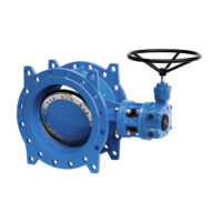
Robinet-vanne papillon à brides DN 350
Robinet-vanne papillon à brides DN 400
Robinet-vanne papillon à brides DN 500
Robinet-vanne papillon à brides DN 700
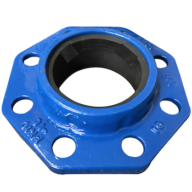
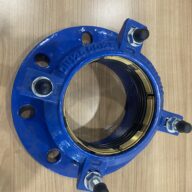
Manchettes courantes en fonte à brides
Manchette fonte DN 500
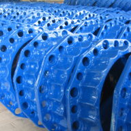
Manchettes d’ancrage – longueur 1,5 m
Manchette d’ancrage en DN 500
Manchette d’ancrage en DN 700
Manchon DN 500
Pièce de raccordement DN 4100
Pièce de raccordement DN 700
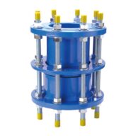
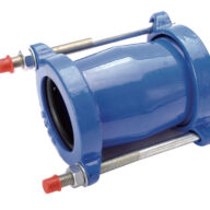
Joint de démontage auto-buté
Joint de démontage auto-buté DN 350
Joint de démontage auto-buté DN 400
Joint de démontage auto-buté DN 500
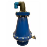
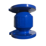
Clapet anti retour DN 350
Collecteur d’aspiration DN 700
Collecteur de refoulement DN 500
Conduite d’aspiration DN 400
Conduite de refoulement DN 350
Coude 45° à deux brides DN500
Bouts unis DN 500 ;
Bout uni DN 600
Bouts unis DN 700 ;
Bouts unis DN 800 ;
Manchettes de traversée à 2 brides avec collerette DN 500 en acier de longueur 2 m;
Manchette de traversée à 1 bride avec collerette DN 500, long 1,5 m + coude
Manchettes de traversée à 2 brides avec collerette DN 700 ;
Manchette de traversée à 2 brides avec collerette DN 600 de longueur 2 m
Manchettes de traversée à 2 brides avec collerette DN 800 ;
Manchette de traversée à 1 bride coudée avec collerette DN 600 + coude
Cônes de réduction à deux brides DN 500/400 ;
Cône de réduction DN500/300
Cônes de réduction à deux brides DN 800/600 ;
Coude 90° à 2 brides DN600
Coude 45° à deux brides DN600
Coude 90° à patin à 2 brides DN600
Coude 90° à patin à 2 brides DN500
Coude 11,25° à 2 brides DN500
Coude 90° à 2 brides DN500
Coude 45° à deux brides DN600
Té à trois brides DN500/500/500
Té à 3 brides DN 600/600/600
Elément de tuyauterie à 2 brides DN 300 en acier de longueur 2 m environ ;
Elément de tuyauterie à 2 brides DN 500 en acier de longueur 2 m ; ;
Eléments de tuyauterie à 2 brides DN 800 en acier de longueur 1,5 m ;
Eléments de tuyauterie à 2 brides DN 600 en acier de longueur 1,5 m ;
Eléments de tuyauterie à 2 brides DN 700 en acier de longueur 1,5 m ;
Entonnoir à une bride en acier DN 500 ;
Joint de démontage DN 500 mm ;
Vannes à papillon DN 500 mm ;
Bout uni d’ancrage et d’étanchéité à bride avec collerette DN300
Joint de démontage DN 700 mm ;
Joint de démontage DN 500 mm ;
Joint de démontage DN 300 ;
Joint de démontage DN 800 mm ;
Joint de démontage DN 600 mm ;
Vannes à papillon DN 700 mm ;
Vannes à papillon DN 800 mm ;
Vannes à papillon DN 600 mm ;
Vannes à papillon DN 500 mm ;
Une vanne altimétrique DN 600 ;
Une vanne altimétrique DN 500 ;
Vanne à passage directe DN 300 ;
Crépine en inox DN 800 ;
Crépine en inox DN 700 ;
Crépine DN 500 en inox
Plaque pleine DN 500
Joint Waterstop
| Supply of plumbing equipment |
| DN 350 flanged butterfly gate valve |
| DN 400 flanged butterfly gate valve |
| DN 500 flanged butterfly gate valve |
| DN 700 flanged butterfly gate valve |
| Standard cast iron flanged sleeves |
| Cast iron sleeve DN 500 |
| Anchor sleeves – length 1.5 m |
| DN 500 anchor sleeve |
| DN 700 anchor sleeve |
| DN 500 sleeve |
| DN 4100 connecting piece |
| DN 700 connecting piece |
| Self-locking dismantling joint |
| Self-locking dismantling joint DN 350 |
| Self-locking dismantling joint DN 400 |
| Self-locking dismantling joint DN 500 |
| DN 350 non-return valve |
| DN 700 Suction Manifold |
| DN 500 discharge manifold |
| DN 400 suction pipe |
| DN 350 discharge pipe |
| 45° elbow with two flanges DN500 |
| Plain ends DN 500; |
| Plain end DN 600 |
| Plain ends DN 700; |
| Plain ends DN 800; |
| 2-flange DN 500 steel crossing sleeves with collar, 2 m long; |
| Single-flange duct fitting with DN 500 flange, 1.5 m long + elbow |
| 2-flange through-sleeve sleeves with DN 700 collar; |
| 2-flange DN 600 2m long through sleeve with collar |
| 2-flange through-pass sleeves with DN 800 collar; |
| Cross-section sleeve with 1 elbow flange and DN 600 collar + elbow |
| DN 500/400 double flanged reducing cones; |
| DN500/300 Reducing Cone |
| DN 800/600 double flanged reducing cones; |
| 90° elbow with 2 flanges DN600 |
| 45° elbow with two flanges DN600 |
| DN600 90° elbow with 2-flange pad |
| 90° elbow with 2-flange pad DN500 |
| 11.25° elbow with 2 flanges DN500 |
| 90° elbow with 2 flanges DN500 |
| 45° elbow with two flanges DN600 |
| Three-flange tee DN500/500/500 |
| 3-flange tee DN 600/600/600 |
| DN 300 2-flange steel pipe element approximately 2 m long; |
| DN 500 steel pipe element with 2 flanges, 2 m long; |
| DN 800 2-flange steel piping elements, 1.5 m long; |
| DN 600 2-flange steel piping elements, 1.5 m long; |
| DN 700 2-flange steel piping elements, 1.5 m long; |
| DN 500 steel single flange funnel; |
| Dismantling joint DN 500 mm; |
| Butterfly valves DN 500 mm; |
| Plain end flanged anchoring and sealing fitting with DN300 collar |
| Dismantling joint DN 700 mm; |
| Dismantling joint DN 500 mm; |
| DN 300 dismantling joint; |
| Dismantling joint DN 800 mm; |
| DN 600 mm dismantling joint; |
| Butterfly valves DN 700 mm; |
| Butterfly valves DN 800 mm; |
| Butterfly valves DN 600 mm; |
| Butterfly valves DN 500 mm; |
| A DN 600 altimetric valve; |
| A DN 500 altimetric valve; |
| DN 300 straight-through valve; |
| DN 800 stainless steel strainer; |
| DN 700 stainless steel strainer; |
| DN 500 stainless steel strainer |
| Solid plate DN 500 |
| Joint Waterstop |
- SPECIFICATIONS RELATING TO MATERIALS AND SUPPLIES – HYDRAULIC CONNECTION NETWORKS
- Material selection – basic solution
The choice of pipeline type (hydraulic connections between the structures to be built / existing ones) selected for the basic solution is as follows:
- Ductile iron pipes for buried and overhead network sections, as well as for drain lines for ground-level tanks,
- 316L stainless steel piping (AISI/SIS standard) is used for network sections directly subjected to alternating phases of immersion and emersion, and more generally to a corrosive atmosphere (particularly in tanks). Note: Exceptions may be considered if these materials are incompatible with mechanical constraints. These exceptions must be approved by the project manager.
- PVC/ HDPE pipesfor buried overflow pipes, stormwater drainage systems
Pipelines must meet all normal conditions or constraints of use, particularly with regard to internal pressure, external loads and the reaction of the soil and supports.
In all cases, the pipes selected for the work will comply with the standards that define their performance, testing conditions and identification.
If ductile iron is chosen as the material, the pipes to be laid under this lot will have the following detailed characteristics:
- Ductile iron in compliance with ISO 2531: 2009 and EN 545: 2010 standards :
- interlocking when buried,
- flanged when installed in elevation (in accessible civil engineering structures) or installed overhead
- Pressure class adapted to design pressures and according to ISO 2531:2009 and EN 545:2010. By default, for each diameter, the pressure class must conform to the preferred class specified by the aforementioned standards:
- For DN 300 pipes: class C40, allowing 40 bar PFA (allowable operating pressure = maximum allowable pressure without water hammer)
- For pipes DN 350 to 600: class C30, allowing 30 bar PFA (allowable operating pressure = maximum allowable pressure without water hammer)
- For pipes DN 700 to 900: class C25, allowing 25 bar PFA (allowable operating pressure = maximum allowable pressure without water hammer)
- Pressure class suitable for design pressures ,
- 2531: 2009 and EN 545: 2010 standards ,
- Wall thickness is defined by ISO 2531:2009. It will be checked at the manufacturer’s factory, for each pipe, along its entire length, to guarantee compliance with this standard. To verify this compliance, the manufacturer will be equipped with a calibrated system for checking the pipe wall thickness along its entire length. The number of measurements must be sufficient, with at least 10,000 checkpoints performed automatically.
- Internal pipe lining:
- mortar conforming to EN 197-1, sulfate resistant, applied by centrifugation and food grade in accordance with ISO 4179:2005.
- in the case of transporting aggressive water (raw water), internal lining = polyurethane (in accordance with standard EN 15655: 2009).
- fittings internally coated with epoxy powder according to EN 14901: 2006,
- coatings holding a certificate of suitability for contact with drinking water, issued by a health authority deemed competent by the project owner.
- External coating of the pipes:
- zinc in compliance with ISO 8179: 2004 and EN 545: 2010 standards ,
- coating on metallic zinc, in accordance with EN 545: 2010 and ISO 8179: 2004,
- fittings externally coated with epoxy powder according to EN 14901: 2006,
- For challenging conditions (extremely aggressive soils, very low resistivity and/or low pH), the pipes will be externally protected by a polyurethane coating conforming to EN 15189: 2007. This coating will be particularly recommended when crossing identified watercourses. In this case, the fittings will be powder-coated with epoxy according to EN 14901: 2006.
- Push-fit pipes – connection between pipes:
- On linear sections = standard type automatic joint,
- rings conforming to ISO 4633: 2002 and EN 545: 2010 and meeting food safety requirements. The EPDM sealing ring will be manufactured by the same manufacturer as the pipes, fittings, and valves to ensure a watertight seal.
- In order to optimize the layout and save on large diameter fittings, the angular deflection allowed by the joints must be sufficient to create curves with large radii. To achieve this, the joints of the push-fit pipes must allow the following angular deflections, in accordance with ISO 2531: 2009 and EN 545: 2010 standards ;
- At the level of special parts (tee, elbow, cone) and when laying on steep slopes, if concrete foundations are not feasible or if the Company prefers to lock its pipes, the locking solutions chosen must have separate sealing and locking functions, and without bolts.
- Flanged pipes – joint between pipes:
- centrifugally spun and flanged welded in accordance with ISO 2531:2009 and EN 545:2010,
- washer will have a minimum thickness of 3 mm (thickness and width sufficient to guarantee the seal of the assembly under the test pressure). To facilitate their installation, they will be of the “metal-reinforced” type.
- The material for the flange gasket washers will be an EPDM elastomer conforming to ISO 4633.
- pressure (PN) must be greater than the maximum operating pressure established in the pipe element plus 10% plus 2 bar.
- flanges with a nominal pressure rating of at least 10 bar,
- Assembly bolts , made of stainless steel, must have the standard nominal diameter for the flange used.
Within the scope of this lot, at the points where horizontal drilling is carried out, the conduits will have the following detailed characteristics:
- New steel tubes – no reused tubes;
- Longitudinally welded rolled tubes with metal filler for DN > 400 mm;
- Steel quality at least equal to industry standard tariff 10;
- Minimum tube thickness at least equal to 1/100 of the inner diameter;
- Length of bars supplied adapted to the dimensions of the entry well;
- Pipe weldable on site by approved welders whose qualifications must be renewed and updated by an official body.
Ductile iron pipes must comply with ISO 2531:2009 and EN 545:2010 standards.
This conformity will be attested by certificates issued by top-tier third-party certification bodies: the certification body must be accredited by an EA member ( European) (cooperation for Accreditation ). The full list of members is available on the website:
http://www.european-accreditation.org/content/ea/members.htm
The manufacturer will provide an ISO 9001:2008 certificate, the scope of which will include the production and marketing of all products offered by the manufacturer. The manufacturer must also provide its Quality Control Plan certified by a leading, independent third-party organization (Bureau Veritas, Lloyds, etc. ).
The End Customer may, if they wish, appoint a third-party inspection body. This body must verify and assess, in the presence of a representative of the End Customer, the certificates provided by the manufacturer , in accordance with standard EN 10204:2004.
All certificates must be provided in French.
Manufacturer reliability
The manufacturer must provide examples of projects of equivalent size dating back at least 10 years, including project specifications, including diameters, specific coatings and locking systems.
These projects must at least be defined as follows: project name, country, end customer, year of delivery, pipe type and diameters, coating type, locking type if applicable, tonnage.
Health and environmental compliance
Certificates guaranteeing the food safety of products that come into contact with transported water must be provided, such as cement mortar, jointing rings, and other coatings, as well as exterior coatings, repair kits, and lubricating paste. Testing must be carried out in accordance with current European health regulations.
Sanitary Conformity Certificates (ACS) are required .
The manufacturer will need to provide an ISO 14001 certificate , certifying environmental management and its control.
In general, the stainless steel to be used will be type 316L (AISI/SIS nomenclature), for parts with a predominant risk of corrosion or assembled by welding.
The welded stainless steel pipes are calibrated at both ends and beveled. The ends are capped, and the interior is passivated and free of oil and grease. The material quality is stamped on each component with indelible ink. The pipes and special fittings are installed carefully and precisely using appropriate tools (plastic straps, austenitic tools, etc.).
The elbows have the same thickness as the pipes.
The reductions are concentric as much as possible. The minimum thickness is at least that of the smallest diameter pipe.
The thicknesses are also chosen according to static and dynamic stresses.
Flanged assemblies are made using raised flanges and free flanges. Small fittings are also made of stainless steel. To prevent electrochemical deterioration, screws and nuts must be interchanged.
The steels used for the manufacture of the flanges must be of the same grade as those of the tubes to which they are welded.
Cast iron flanges are prohibited.
The seals are of a quality appropriate to the fluid being transported and conform to the piping specifications.
The joint faces are raised and flat for butterfly valve connections.
For nominal pressures above 25 bar, the seals are drilled so that the assembly bolts can pass through them.
For tees, elbows, reducers etc… commercially available prefabricated fittings are used as much as possible in shades appropriate to the tubes to which they are welded.
Only large radius bends within the tube and non-standard unequal tees can be fabricated. The method of manufacturing these fabricated parts is subject to the prior agreement of the project manager.
The diverging and converging sections are made of steel of the same grade and thickness as that used for the tubes. The length of an element is at least equal to 7 times the difference in diameters.
Welded assemblies with diameters less than DN 50 are made using welded push-fit fittings.
The bends will conform to standard NFA 49.182 “Weldable bends in steel tubing, model 3d”. The diverging and converging bends will be made of steel of the same grade and thickness as that used for the tubes.
The upper generator of a divergent or convergent inserted into a pump suction line must be horizontal.
The piping elements are assembled by steel flanges, with machined faces, conforming to NF standards of the 29000 series. The nominal pressure of the flanges (PN) must be greater than the maximum design pressure, plus 10% plus 2 bars.
For nominal pressures above 25 bar, the flanges must be push-fit.
Unless otherwise specified, the flanges must have a nominal pressure of at least 10 bars.
The assembly bolts, made of stainless steel, must have the standard nominal diameter for the flange used.
The sealing gaskets between the flanges are made of a flexible material. They must have sufficient thickness and width to ensure the assembly remains leak-proof under the test pressure. For nominal pressures above 25 bar, the gaskets are drilled to allow the assembly bolts to pass through.
The pipes and elements of the rainwater drainage networks will be made of category SN8 PVC with standard joints conforming to standard NF P16-362.
The PVC pipes will have the following characteristics:
- with structured walls,
- pipe resistance class SN8 (8 KN/m²),
- Chamfered male end with a depth marking for insertion,
- Tulip- shaped female end with an integrated sealing gasket,
- elastomer sealing ring ,
The pipe lengths will be 3m and 6m.
The fittings will be:
- iron for flanged fittings (tees, plain flanges, push-fit flanges, …)
- cast iron for elbows, reducers and plugs
- cast iron for tees allowing the connection of PVC pipes without a shut-off valve (3-way tees).
All documents will include the following information:
- manufacturer’s name and acronym,
- part designation ,
- year of manufacture.
- Origin and mandatory marking
All non-standard pipes and products must be subject to a “favorable technical opinion” from an international technical commission.
Product standards must prescribe the marking.
Each component, or, where this is not possible, each package of products, must be marked in a durable and clearly visible manner.
In order to definitively identify the components, the following minimum information must be provided:
- identification of the product standard number, i.e. ISO, EN or NF XXXX;
- identification of the manufacturer and place of production;
- the type of pipe and its resistance class,
- identification of the year of manufacture;
- identification , where applicable, of the certification body;
- class identification , where applicable;
- identification , where applicable, of suitability for use in contact with drinking water.
In all cases, the contractor must verify that the class or series used is compatible with the conditions specified in Chapter II of CCTG booklet no. 71. It will be their responsibility to inform the project manager of any anomalies they identify and any modifications they deem appropriate.
Pipes, joints, elbows and special parts or fittings must come from the same manufacturer.
- Equipment, taps and accessories
These valves (of large sections) are located on the new main discharge/transfer network.
Butterfly valves will conform to article 22-1 of CCTG fascicle 71.
They will have the following characteristics:
- Direct passage,
- Flanged fittings,
- Two-way sealing:
- Solid stainless steel seat, added separately.
- Heel joint trapped between the butterfly and its flange.
- Body and butterfly valve made of GS cast iron coated internally and externally with oven-cured epoxy powder: minimum thickness 150 µm,
- EPDM heel seal
- Solid stainless steel seat,
- Stainless steel swivel shaft,
- Bronze bearing,
- Steel screws.
- Order type and closing direction:
- The closing direction is the same as that of a clock.
- When installed in a room, chamber, or inside structures: manual control via a handwheel. Additionally, an external indicator allows for constant monitoring of the butterfly valve’s position.
The maximum operating pressures of the gate valves will be adapted to the design pressures ( see § 2) of the pipes on which they will be installed.
This type of valve must be perfectly watertight under these pressures.
These valves (of small sections) are located on the drainage networks, with a diameter of 200mm.
Gate valves will conform to article 21-1 of CCTG fascicle 71.
They will have the following characteristics:
- Direct passage,
- Flanged fittings,
- Waterproofing:
- Perfectly closed valve: compression of the elastomer of the lid,
- A removable pressure-operated sealing bearing ensures sealing to the outside and prevents the entry of foreign bodies.
- Body and lid in GS cast iron coated inside and outside with oven-cured epoxy powder: minimum thickness 150 µ.
- The screws securing the body and the cover have countersunk heads covered with a plastic protector.
- Overmolded elastomer lid.
- Stainless steel operating screw.
- Interchangeable brass operating nut.
- Bronze screw bearing.
- Order type and closing direction:
- The closing direction is the same as that of a clock.
- For underground installations: controls via key-operated valve.
- In case of installation opposite, in a chamber or inside structures: manual control by a handwheel.
The maximum operating pressures of the gate valves will be adapted to the design pressures (see § 2.3.2) of the pipes on which they will be installed.
This type of valve must be perfectly watertight under these pressures.
An annular valve will regulate the water supply to the new sites at Sotuba , Doumanzana, and Moribabougou . It will have the following characteristics:
- Function = Motorized regulating valve controlled by a 4-20mA type control input signal to reduce and permanently control the flow without causing cavitation or vibration.
- PFA adapted to the design pressures (see § 2.3.2), minimum 10 bar
- EN 1092-2 PN10 type 21 flanges
- Design :
- Electrically controlled, linked to a water level
- Ductile iron EN-JS1050 (GGG-50)
- Piston: Stainless Steel
- Shaft: Stainless Steel
- Piston seal: EPDM
- O-rings: NBR
- Coating: blue color RAL 5015
- Interior and exterior: Epoxy powder
- By electric servomotor Type SAR 07.6 speed 22 rpm and device allowing to have on the servomotor a local/remote control and allowing the positioning of the motor via a 4-20mA info.
- Closure: Multi-turn
- Power supply: 380 volts 50Hz Three-phase
- Protection: IP68
- Manual emergency steering wheel with disengageable clutch
- 4-20mA control input
- 2 full-bore pressure gauge valves
- 1 protected visual opening indicator with manual purge
- 1 RFO opening and closing retarder
Altimetric valve
An elevation valve will regulate the water supply to the new sites at Sotuba , Doumanzana, and Moribabougou . It will have the following minimum characteristics :
- Function = Control valve controlled by the setpoint pressure defined to control the opening and closing of the water inlet into the tanks.
- PFA adapted to the design pressures (see § 2.3.2), minimum 10 bar
- EN 1092-2 PN10 type 21 flanges
- Design :
- Controlled by altimeter pilot
- Ductile iron EN-JS1050 (GGG-50)
- Tubes and valves: Stainless steel
- Axle, rod, guide ring : Stainless steel
- Shutter: Stainless steel
- Coating: blue color RAL 5015
- Interior and exterior: Epoxy powder
- 2 full-bore pressure gauge valves
- 1 visual position indicator
- Electromagnetic flow meter
The flow meters specified in this contract are located:
- 01 at the arrival of the DN500 pipeline at the Sotuba reservoir and 1 at the outlet of the Sotuba pumping station towards the Douanzana reservoir ,
- Doumanzana distribution pipeline and 01 on the transfer pipeline to Moribabougou
- 01 on the distribution pipeline of Moribabougou
They will all be of the electromagnetic flowmeter type.
The principle of flow measurement is based on Faraday’s law. The voltage induced by a conductor moving through a magnetic field is directly proportional to the conductor’s speed. The voltage is then measured across two diametrically opposed electrodes. It is proportional to the magnetic field, the distance between the two electrodes, and the average fluid velocity.
They will have the following nominal characteristics:
- DN adapted to different locations;
- Flanged fittings;
- Steel body;
- Coating suitable for the type of fluid being transported;
- Speed range 0.03 to 10 m/s
- IP68 Protection Class
- Accuracy ± 0.25% of instantaneous flow rate;
- Power supply
- 4 programmable logic outputs,
- LCD screen,
- USB interface.
To allow for future verification of the data provided by the electromagnetic flow meter, a service tap with a minimum bore of 25 mm (1″ BSP thread) is to be installed on the network. This installation must allow for the insertion of an insertion flow sensor into the network.
The Company will have to position this intake valve according to the straight length distances (upstream/downstream) to be respected.
The flow meters will be 24 volts.
Sotuba pumping stations but also at the connection of the supply pipes to Doumanzana (DN900 from Missira and DN500 from Sotuba ) will have the following characteristics
- Double beater
- GS cast iron body with epoxy coating
- CF-8M stainless steel swing gates
- Stainless steel axle and 316 stainless steel spring
- EPDM gasket
To facilitate the assembly and disassembly of tap fittings, it is planned to couple the tap parts by implementing a disassembly joint with the following characteristics:
- Long-stroke self-removing stop seal for flanged taps
- Minimum travel of 40mm,
- Fixed body, counter-flange, sliding body and tie rods in EN 10025 S235JRG2 carbon steel,
- EPDM type elastomer seal
- PFA adapted to the design pressures ( see § 2.3.2 ), minimum 10 bar,
- Compliant with standard NFE 29220,
- The sliding body strap is of the heel type.
- Backfill materials
French standards
- NF P98 331 Roads and adjacent areas – trenches: opening, backfilling, repair
- Backfill using materials from the site (reuse)
The excavated materials will preferably be reused from the previously excavated stockpile.
These materials will be reusable if they are clean, non-clayey sand or laterite. Any clayey or silty pockets must be removed and replaced with clean sand or water-resistant gravel. This excavated material must not contain tree roots, topsoil, or organic matter. Non-compactable materials (clay, loam), as well as rocky materials, will also be rejected. Excavated material containing a high percentage of gravel must be mixed with soil before being used for backfilling.
Reuse of excavated material will only be permitted after soil identification through GTR soil analysis (Road Earthworks Guide) with determination of its moisture content. Indeed, in accordance with standard NF P98 331, the materials usable in trenches are as follows:
- Backfill made of imported materials
If necessary, backfilling may be carried out using imported materials, according to the following specifications:
For the Lower Embankment (PIR) and in the encasement zone
Table 7 : Usable backfill in the lower part of the backfill (Extract from standard NF P98 331)
For the Upper Embankment Section (PSR)
Table 8 : Usable backfill in the upper part of the backfill (Extract from standard NF P98 331)
In all cases, the materials used for bedding, encapsulation of structures or backfill must be of such a nature as to allow backfilling of trenches in accordance with the specifications of booklet 71.
In the case of laterite track repair, the trench is backfilled up to the level of the natural ground level, in successive layers properly compacted.
The materials used are preferably sourced from the stock of excavated material from preliminary earthworks.
|